The ARC4 is used to command VANTEC speed controls or servos directly from analog joysticks. It is designed to mount inside the RDFR33 to RDFR63E series. Of course it may be operated entirely independently. Like its WWII namesake, the ancient ARC5 radio set, the ARC4 is a link to the past. The ARC4 has four separate and distinct analog inputs called S, T, 3 and 4, (remember analog?) and four corresponding Servo Command Pulse outputs. It consists of an unpackaged PWBoard and requires 9-13 volts @ 25 ma. |
The analog inputs are scaled to accept normal Futaba joystick voltages. In many joysticks, the potentiometers are 5000 to 10000 ohms and are mechanically and electrically centered with a centered joystick handle. A voltage of 5 volts is applied across the resistance element to excite the joystick; thus the centered output voltage is 2.5 volts. The joystick pots usually contain normal resistor elements that have a possible rotation of about 300 degrees. However, the joystick handles only move about +-40 degrees, a total of 80 degrees. Therefore the available voltage swing output from the joystick is constrained to about a volt going from 2 to 3 volts |
Before modern digital trims, joysticks were centered precisely by summing a correcting voltage from a separate trimming pot. The trimming pot is also excited by 5 volts and is coupled to the joystick pot output by about 22K ohms to limit its authority to effect the joystick output. The ARC4 is factory calibrated to consider the effects of this connection but the range scaling trim pot, labeled "502" can be adjusted. CCW is more range = greater servo travel. |
There is a single Centering adjustment for the ARC4 itself, the trimpot labeled "103". The inputs to the ARC4 are internally set to 2.5 volts when there is no joystick or analog voltage input. This facilitates the proper Centering procedure with the joysticks disconnected. The nominal Futaba centered pulse width of 1.52 ms is factory calibrated. In most applications an oscilloscope or calibrated servo can be used to change this adjustment. There may be some interaction between the Centering and the Range trimpots. |
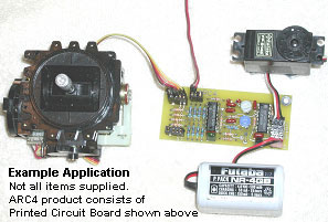
See the picture below to reference the following descriptions.
The ARC4 analog inputs are paired using two 4 pin female W.S. Deans connectors. Male mates with solder tails supplied. (Another blast from the past!)
Analog input connector in lower left hand corner with S T label:
Ground =Lone pin
Polarizing space
+5V excitation
S=analog or joystick (steering)
T=analog or joystick (throttle) |
 |
Analog input connector in upper left hand corner with 3 4 label:
Ground =Lone pin
Polarizing space
+5V excitation
3= analog or joystick input 3
4=analog or joystick input 4
The pulse output is compatible with most radio control devices like servos, speed controls, and proprietary switches. It's very similar to the output of a Futaba receiver and the normal range is 1.1 to 1.9 ms. These Servo Command Pulses are positive pulse 5 volt output current limited by the MC14017BCP CMOS output chip to 1-2 ma. These are presented on the ARC4 in conventional Futaba .1" spacing headers clustered at the right end of the PWBoard adjacent to the MC14017BCP IC and labeled to correspond to the S, T, 3, and 4 inputs. However, they are not polarity keyed on the ARC4 so be careful when connecting your R/C devices. |
Ground = pins adjacent edge of end of board, with 3, 4, T, S labels
+5 =middle pins
SCPulse =pins adjacent MC14017BCP IC
Note that the +5 volts for the Servo Command Pulse outputs must be separately supplied to the lone 3 pin .1" header in the lower right hand corner of the board. This is just like the battery connection for a Futaba receiver. The current required is entirely dependent upon the total requirements for the attached R/C devices. This could range from virtually nothing to amperes. VANTEC speed controls do not require the 5 volts. |
Ground = pin adjacent lower right hand corner of board and clearly labled "G"
+5 =middle pin
SCPulse =pin near TO92 transistor, not used
|
The ARC4 requires power itself, nominally 12 V. A W.S. Deans male connector is mounted on the ARC4 PWBoard near the "ARC4" designation on the board itself. A mating female is supplied. Pin assignment is similar to the old Ace radio
Not used =Lone pin
Polarizing space
+12V @ 25ma
Ground
|
The ARC4 uses the NE5044 encoder to generate a PPM R/C data stream from analog inputs which is then decoded into separate SCPulse outputs by a MC14017BCP Johnson counter.
The ARC4 comes with a limited one-year warranty based upon a fixed repair charge for units not tampered with or abused as determined by us. |