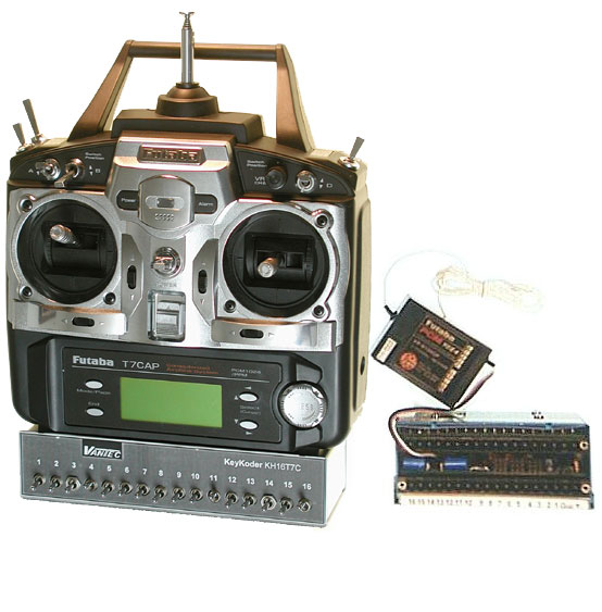
| The KH712, KH716 and KH732 Hitchiker Radio Control systems combine Futaba's excellent PCM1024 radio systems with VANTEC KeyKoder technology to add the extra channels and functions needed for Special EFX projects, inspection/sample harvesting vehicles, and tele-operated robots. Great for controlling submarines with their complex plumbing and pumps. Making your dream scale R/C boat
fully operational is now easier than ever. Eliminate fussy servo-microswitch kluges. Microprocessor equipped projects have used the Hitchiker channels to initiate pre-programmed routines. Available on 72 or 75 MHz frequencies;
there is no additional charge to have your transmitter legal. VANTEC warrantees the entire system..
The three systems are complete including the latest Futaba PCM radio, transmitter, receiver, charger and the VANTEC Hitchiker KeyKoder components. The Futaba radio sets are top-of-the-line models using Futaba's PCM1024 Pulse Code Modulation method. PCM is a siginificant improvement over FM because it transmits the servo commands as digital words with special mathematical properties that facilitate accurate reception and calibrate servo positions for Fail Safe operation. Servo jitters are a thing of the past. The F/S meets the criteria for competitive robot safety shut-down. To read more about the PCM Advantage follow this link.
VANTEC fully harnesses Futaba's coding to reliably pack additional controls onto one of the Futaba R/C servo channels. The new controls are independent and operate simultaneously. The remaining conventional channels are not affected. To make a complete Hitchiker system VANTEC adds two devices to the Futaba set. The first device is a KeyPad that is added to the transmitter. It mounts onto the base of the Futaba transmitter. Each new KeyPad channel is actuated by a special toggle switch that can operate momentarily like a push button by pressing down; it automatically springs back to center off. Or switch it "On" continuously like a normal toggle switch by flipping it up. Any number of switches may be activated at once. The KeyPad switches are labeled 1-16 or 1-32.
The KeyPad understands and "speaks" PCM1024; it interjects its new data onto one of the regular servo channels through the trainer connector. This means you lose the normal operation of the selected channel; usually the invisible 8th channel of a 7 channel system or the "Retract" channel 5 is sacrificed. The second device is a Receptor add-on box that plugs into the Futaba R/C receiver like a servo and separates the KeyPad commands back into 12, 16 or 32 individual outputs corresponding to the transmitter KeyPad switches. The Futaba receiver is optically isolated from the workings of the Receptor. The Receptor has terminal blocks and additional servo connectors for the newly added channels. These on-off or two-state outputs manifest themselves several ways depending upon the Receptor model. At 5A capability each, the ON-OFF electronic switches can be used directly for many functions, even with devices operating on an assortment of voltages. And the 8 conventional Servo Command Pulse outputs are a handy and familiar way to implement mechanical functions using conventional servos.
 |
The KH716 complete system has 7 conventional servo channels and 16 independent and simultaneous KeyKoder ON-OFF electronic switch channels for 23 channels total. The first 8 of the 16 KeyKoder channels coincidentally feature 2 three-position regular Servo Command Pulse outputs and 6 two-position regular SCP command outputs. The KH716 system consists of: the complete Futaba PCM set with the 7 channel FPR168DP or other equivalent Futaba Brand receiver, VANTEC KH16T KeyPad and KH16R Receptor. Servos available.
The KH732 complete system has 7 conventional servo channels and 32 independent and simultaneous KeyKoder ON-OFF switch channels to yield 39 channels total. The first 8 of the 16 KeyKoder channels coincidentally feature 2 three-position regular Servo Command Pulse outputs, 6 two-position regular SCP outputs. The KH732 systems consists of: the complete Futaba PCM R/C set, with the 7 channel FPR168DP or equivalent Futaba brand receiver,
VANTEC KH32T KeyPad and KH32R Receptor.. Servos available. Generally the 716 & 732 versions are employed in boats and robots. Up to 128 ON-OFF channels can be added to a single Futaba Servo Channel with an array of KeyKoders The KH712 is specifically configured for model aircraft applications. Switches 1 through 8 on the KH16T KeyPad generate only Servo Command Pulses and switches 13, 14, 15, and 16 are the only electronic switch outputs on the KH12R Receptor. The KH712 Hitchiker is perfect for 1/4 scale R/C model airplanes with 7 conventional servo channels for the normal flying functions and 12 added KeyKoder channels for a total of 19 channels. It's KeyKoder Receptor features 2 three-position regular Servo Command Pulse outputs,
6 two-position regular servo command outputs, and 4 electronic switches. Since the servo command outputs are just like the signals coming from a Futaba receiver you can plug-in up to 8 new conventional servos for auxiliary functions like bomb bay doors, bomb release, or parachutists. The electronic switches can be used to control engine ignition, starting, lights and camera. The KH712 system consists of Futaba PCM R/C set with an 8 channel receiver, VANTEC KH16T KeyPad and KH12R Receptor. TRANSMITTER / KEYPAD INSTALLATION: The KeyPad is factory mounted to the Futaba case, a slight modification made to the transmitter. You cannot use the original trainer feature after these modifications. KH716R & KH732R RECEPTOR INSTALLATION: Keep all output wiring separated from the Futaba receiver and servo leads. Use the full extended length of the supplied receiver antenna and locate it away from all other wires and metal structures. Plug the Receptor add-on box into the Futaba R/C receiver channel engraved "K", usually Futaba channel 5. FPR168DP and FPR138DP receivers ordered from VANTEC for KeyKoder applications have a small internal modification to
supply the needed signal out the "K" marked channel. It is the same as the "C" or DSC connector available on other Futaba PCM1024 receivers. Do not plug a servo into this channel as it will disable all channels.
Some receivers like the FP-R129DP come with a "C" or DSC output; plug the Receptor into this socket regardless of the Futaba channel sacrificed for the Hitchiker. Receptor Servo Command Pulse outputs work in conjunction with KeyPad channels 1-8. With KH16R and KH32R receptors these SCPulse outputs operate together coincidentally with ON-OFF outputs 1-8. These Servo Command Pulse outputs are limited to two or three fixed pre-determined positions and can drive regular R/C servos or
speed controls. Regular 3 pin plugin servo connections are provided on the Receptor in three groups, each group accepting 3 servo connectors netting 9 Futaba "J" style connectors in all. The 9th position labeled "Bat", on the far right, is the power input to run the 8 Receptor servos. A separate 4.8V battery pack or suitably robust 5V regulator for this is recommended.
Servo Command Pulse outputs "1-2" and "3-4" are the three position servo outputs. Logically 2 switches on the KeyPad are required to define 3 positions (4th possibility not used). Further, the two and three positions are designed so that a three position servo output shares a transmitter KeyPad switch with a two position servo output. For example: KSw1 controls servo SCP1 which operates as two position actuator. But KSw1 also commands the second SCP2 servo, along with KSw2, for one of three positions. In practical situations either 2 two-position servos OR 1 three position servo would be deployed. The actual servo positions are assigned in groups to provide a variety of combinations as delineated in Fig 5. The three positions are adjustable by three factory set and secured trimming potentiometers. Receptor ON-OFF Switch outputs are each capable of current sinking to ground 0-30 VDC@ 5 amps. This means they switch to ground to complete the circuit to operate your device. Because they switch to ground they easily accomodate a variety of lights, horns, motors and other loads operating on a variety of voltages up to 30VDC by simply using different batteries or taps on a series connected set of batteries. See Figure 1 above for examples. Total continuous "box"
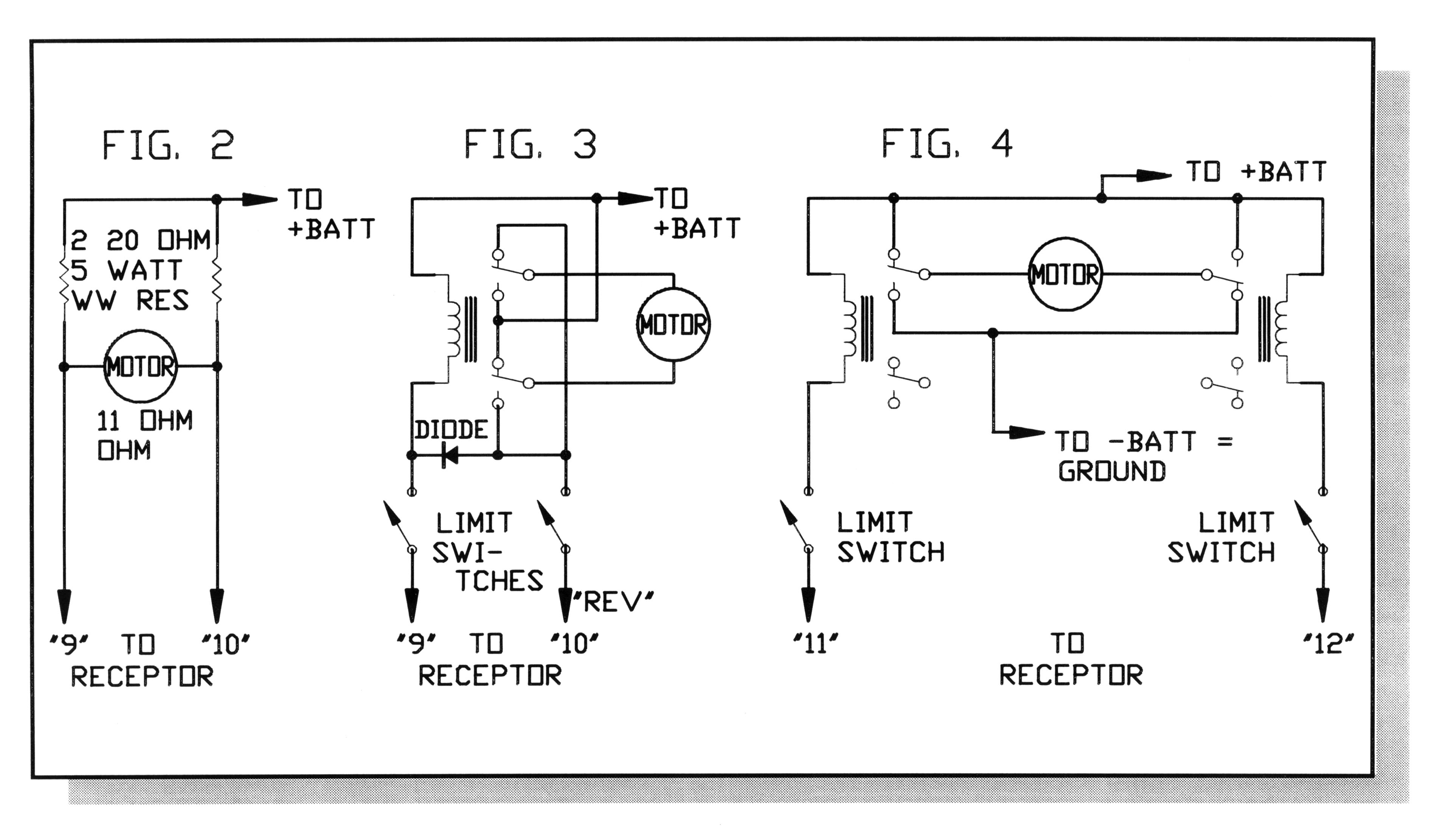
current controlled at any one time should be limited to 20 Amps. Inductive coil loads like motors and relays inherently generate a potentially damaging voltage spike when they are turned off. We recommend the addition of a Metal-Oxide-Varistor (MOV) across each inductive load to safely suppress this spike. VANTEC has supplied a number of MOVs with your Hitchiker. They are unpolarized so you may connect them without regard for position or orientation. Figure 2 shows a simple "lossy" bridge circuit for forward and reverse momentary operation of a small motor such as the zoom and focus motors found in some video cameras. The resistors provide automatic current limiting and un-equal
resistor values can be used for different forward and reverse speeds. Experimentation is required, but for a 12V battery bridge resistors should be greater than 15 ohms; 24V battery - 30 ohms. Put a MOV across the motor brushes. To maintain satisfactory R/C operation select quality motors whose RFI qualities are known from past R/C applications. Some situations may require RF chokes in series. Don't use toy motors with metal brushes or automobile-type horns because these devices generate horrific RF Interference. Relays may be used to amplify the current capacity or provide handy operating logic such as reversing high current motors. Use MOVs across their contacts to minimize RFI as well as in parallel across the coil for spike suppression. Additional MOVs are available from VANTEC or Radio Shack. Use AC types rated for 30-50 volts such as Panasonic ERZ-V05D390. Figure 3 shows efficient operation of reversing motors up to 5 amps using a single 5 amp relay and 5 amp diode from Radio Shack. If your application runs into a physical stop use the limit switches shown to prevent dangerous stalled motor operation. For limit switch installations you can have automatic reverse/return by connecting wire "REV" to ground instead of a Receptor output, omit diode, (saves a KeyKoder channel too). Don't forget the MOVs. Figure 4 shows the use of relays to operate much larger motors, over 4 amps. In this circuit the limit switches need only be capable of handling the relay coil current. Use MOVs. If the Receptor fails to receive KeyPad signals it uses the old information for a brief time and then enters a fail safe mode. In the fail safe mode all electronic switches are turned off except KCh14 & 15 which maintain their last state. You could use KCh14 to command lighting since your vehicle could be at rest but illuminated with the transmitter turned off; great for preventing runway collisions at night or dinner flotillas. KH16R and KH32R Receptor power wiring is through the 18 station plug-in terminal block. The ground circuit which supports these electronic switches-to-ground must be substantial since all the current
for all of your loads passes through it; up to 5 Amps for each one. Use a suitable gauge for the ground wire to support your switch loads; AWG#16 for the full capacity. The ideal power supply for the unit is +12VDC connected to the + terminal of the terminal block .+. The power input range on the + terminal may by 4.8-30VDC. When power is not supplied to the + terminal block then power and ground for the Receptor will be derived automatically from the 4.8VDC power input for the Hitchiker "J" style connector; the 9th one labeled "Bat". This is less desirable due to increased current drain. Power may be supplied to both the terminal block + and "J" style. The "J" style +4.8 will run the servos and the terminal block + will power the internal circuitry.
|